


Views: 0 Author: Site Editor Publish Time: 2026-07-22 Origin: Site


Selecting solar components is not a simple commodity purchase. It represents a 25-year infrastructure investment where minor variations in cell architecture compound into massive differences in Levelized Cost of Energy (LCOE). Procurement teams and system designers face significant challenges navigating the rapid transition from legacy cell structures to advanced n-type architectures. They must balance upfront capital expenditure against long-term degradation risks to ensure project viability. A successful solar power system solution requires grounding procurement decisions in the fundamental mechanics of modern solar photovoltaic technology. Moving beyond marketing claims to verifiable performance metrics and bankability standards is essential for maximizing yield and minimizing risk over the system's operational lifespan. You need to evaluate the physical realities of the hardware, understand the chemical degradation pathways, and align the electrical characteristics with your balance of system components.
Architecture Dictates Yield: The shift from P-type to N-type cells fundamentally alters temperature coefficients and degradation profiles, directly impacting long-term financial modeling.
LCOE Over Nameplate Wattage: Evaluating a solar PV module requires analyzing real-world performance variables—such as Light-Induced Degradation (LID) and bifaciality—rather than relying solely on Standard Test Condition (STC) wattage.
Manufacturer Viability is a Feature: A 25-year performance warranty is only as reliable as the balance sheet of the solar module manufacturer backing it; Tier 1 bankability and supply chain transparency are critical evaluation criteria.
System Integration & Scale: Physical dimensions, voltage characteristics, and DC-to-AC conversion pathways must align strictly with the chosen Balance of System (BOS) components to optimize land use and utility-scale balance-of-plant costs.
The photovoltaic effect involves photons dislodging electrons within a semiconductor lattice to generate Direct Current. Material purity and cell design dictate energy conversion efficiency. High-purity silicon minimizes electron recombination, ensuring maximum current flows through the external circuit. When evaluating a solar PV module, you must look at how effectively the manufacturer manages this internal electron flow. Poor cell design leads to internal resistance, which manifests as heat rather than usable electrical power.
Monocrystalline silicon has become the commercial benchmark for high-performance solar installations due to its continuous crystal lattice and lower recombination rates. Polycrystalline silicon features multiple crystal boundaries that impede electron flow, resulting in lower overall efficiency. We see this difference clearly in field deployments where monocrystalline arrays consistently deliver higher energy density per square meter. This density is a non-negotiable requirement for commercial rooftops with limited space.
Electricity progresses from the DC power generated at the module level through collection circuits to central or string inverters. The inverter interface acts as a primary efficiency bottleneck in any commercial installation, requiring careful voltage matching to minimize clipping losses. If your string voltage exceeds the inverter's maximum input window during cold weather, the system will shut down to protect itself, resulting in lost generation hours.
Primary metrics used to evaluate PV systems at the decision stage include module efficiency, temperature coefficient, annual degradation rate, and cost per watt. These factors directly influence the system's LCOE and long-term financial returns. You cannot rely on STC wattage alone. A 500W module with a poor temperature coefficient will produce less energy in a hot climate than a 480W module with superior thermal stability.
P-type wafers are doped with Boron, while N-type wafers are doped with Phosphorus. The industry is aggressively shifting toward N-type wafers to eliminate early-life degradation mechanisms, such as Light-Induced Degradation (LID), which commonly affect Boron-doped P-type cells. This chemical difference translates directly to the bottom line. N-type cells maintain their initial power rating much longer, providing a higher baseline for your 25-year financial models.
Wafer Type | Dopant | LID Susceptibility | Market Trend |
|---|---|---|---|
P-Type | Boron | High | Phasing Out |
N-Type | Phosphorus | Near Zero | Industry Standard |
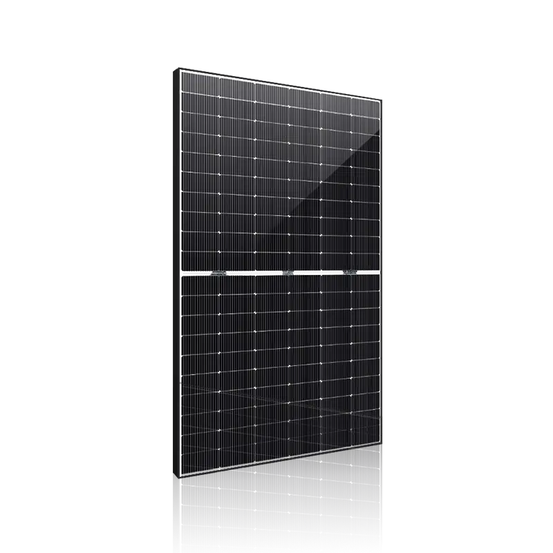
Passivated Emitter and Rear Cell (PERC) technology adds a dielectric passivation layer to reduce electron recombination and reflect unused light back into the cell. The PERC solar module features a highly mature manufacturing process, offering the lowest upfront capital cost and proven historical reliability. However, it is approaching its theoretical efficiency limit of around 23-24% and has a higher susceptibility to degradation compared to newer architectures. For projects where land is cheap and abundant, PERC still offers a viable path to project completion.
Tunnel Oxide Passivated Contact (TOPCon) mechanics focus on an ultra-thin tunnel oxide layer paired with highly doped polycrystalline silicon to minimize carrier recombination. TOPCon solar technology provides superior efficiency ceilings, excellent low-light performance, significantly lower temperature coefficients, and high bifaciality factors up to 85%. While it carries a slight premium on upfront cost, it is rapidly achieving price parity with PERC. The increased energy yield over the system's life easily offsets the initial capital difference.
Heterojunction (HJT) technology utilizes amorphous silicon layers to achieve the highest efficiency but comes at the highest cost. Thin-Film alternatives, such as CdTe and CIGS, offer specific advantages for utility-scale applications or high-temperature microclimates, though they generally have lower baseline efficiencies than crystalline silicon options. HJT requires specialized manufacturing lines, which currently limits its widespread adoption compared to the more easily upgraded TOPCon lines.
Modules perform differently outside of Standard Test Conditions. A module with a lower temperature coefficient, such as -0.30%/°C, will outperform a nominally higher-wattage module in high-heat real-world conditions. Heat reduces voltage output, making the temperature coefficient a critical metric for hot climates. When designing a system for a desert environment, prioritizing thermal stability over raw STC wattage is the only way to guarantee modeled energy yields.
First-year degradation guarantees typically stand at 2% for PERC versus 1% for TOPCon. Linear annual degradation rates also differ, averaging 0.55% for PERC and 0.40% for TOPCon. These fractions significantly impact total energy yield at year 20, making lower degradation architectures far more lucrative over time. A half-percent difference in annual degradation compounds into thousands of megawatt-hours lost over a utility-scale project's lifespan.
High-efficiency modules decrease overall balance-of-plant costs. Higher power density translates directly to fewer structural racks, reduced cabling requirements, shorter trenching lengths, and a smaller overall physical footprint. This efficiency maximizes land use and reduces installation labor. When you increase the wattage per square meter, you spend less on steel, copper, and the labor required to install them.
The trend toward larger wafer sizes, such as M10 and G12, introduces structural and electrical trade-offs. Larger modules pose higher wind and snow load risks and require increased glass thickness. System designers must match module short-circuit current (Isc) with inverter input limits to prevent equipment damage. You cannot simply swap a 182mm wafer module for a 210mm wafer module without recalculating your string sizing and verifying tracker compatibility.
Verify the maximum short-circuit current rating of your selected string inverters.
Check the structural load limits of your racking system against the module's surface area.
Calculate the maximum string length based on the lowest expected site temperature.
Confirm the module frame thickness matches the mounting clamp specifications.
Tier 1 status, defined by BloombergNEF criteria based on non-recourse debt financing, indicates financial stability but does not guarantee product quality. Independent financial vetting of a solar module manufacturer is required to ensure they can honor long-term warranty obligations. You are buying a 25-year financial instrument. If the company goes bankrupt in year five, your performance warranty becomes worthless paper.
Traceability audits, such as the SEIA traceability protocol, ensure compliance with international labor laws and import regulations like the UFLPA in the US. Transparent supply chains mitigate project delays caused by customs detentions and safeguard corporate reputation. You must demand full bill-of-materials traceability from the polysilicon source to the final assembled module before signing any procurement contract.
Product Warranties cover defects in materials and workmanship, typically lasting 12-15 years. Performance Warranties guarantee power output, usually extending 25-30 years. Executing a warranty claim requires strict burden of proof, often necessitating comprehensive site data and third-party testing. Manufacturers will require flash test data and electroluminescence imaging to prove the module failed due to manufacturing defects rather than improper installation.
Larger format modules are highly susceptible to microcracks during shipping and installation. Implementing Electroluminescence (EL) testing protocols upon delivery helps identify hidden damage before installation, preventing long-term performance degradation. A module dropped on a pallet may look perfectly fine to the naked eye, but EL imaging will reveal shattered cells that will eventually form destructive hot spots.
Partial shading disproportionately impacts string performance. Localized shade alters the electrical circuit within a module. Bypass diodes protect against hotspot-induced thermal runaway. Half-cut cell designs or module-level power electronics (MLPE) are required when shading risks are significant. If a single cell is shaded, it acts as a resistor, heating up and dragging down the current of the entire string unless the bypass diode activates.
PERC remains viable for strictly budget-constrained projects with ample space. TOPCon is the definitive choice for maximizing LCOE and long-term yield in footprint-constrained commercial and utility-scale installations. The transition to N-type silicon is complete, and procurement strategies must adapt to these new baseline metrics.
Verify N-type or P-type requirements based on your specific site temperature and space constraints.
Audit manufacturer bankability using independent financial reports, not just marketing brochures.
Confirm inverter and racking compatibility with the specific physical and electrical characteristics of the chosen module.
Request third-party independent engineering reports, such as PVEL or RETC scorecards, to validate performance claims.
Initiate RFP discussions based on strict technical specifications rather than generic wattage requests.
A: A solar cell is the individual semiconductor unit that converts sunlight into electricity. A solar PV module is a collection of cells wired together and framed for protection. A solar array consists of multiple modules connected to form a complete power generation unit.
A: TOPCon utilizes N-type silicon, which offers lower degradation rates, superior low-light performance, and higher efficiency ceilings compared to P-type PERC modules. It mitigates early-life degradation mechanisms, improving long-term energy yield.
A: As temperatures rise, solar panels lose efficiency. The temperature coefficient measures this loss; a lower coefficient means the panel retains more of its rated power in hot conditions, ensuring better real-world performance.
A: Beyond the solar modules, a complete solution includes inverters for DC-to-AC conversion, structural racking, electrical cabling, overcurrent protection devices, and monitoring software to track system performance.
A: Check for Tier 1 bankability status, review third-party testing reports from labs like PVEL or RETC, and conduct independent financial audits to ensure the manufacturer can support 25-year warranty claims.
A: LID is the initial loss of power when a panel is first exposed to sunlight, primarily affecting Boron-doped P-type cells. N-type cells, doped with Phosphorus, effectively mitigate this degradation.
A: Shading on a single cell restricts current flow for the entire string. Bypass diodes activate to route current around the shaded area, preventing hot spots and minimizing overall power drop-offs during partial shading.


